Self Bias Circuit Diagram Patent Review: Self-bias Emitter C
Solution: study of bjt biasing circuit fixed bias and self bias Self bias circuit diagram Jfet circuit channel bias self circuits fet biasing dc voltage electronics projects fixed common gate audiophile modifications mao gr next
Solved Self-Bias 1. Construct circuit as shown in Fig. 4.2 | Chegg.com
Self bias circuit Self bias circuit Jfet: self bias configuration explained (with solved examples)
Self bias circuit diagram
Self bias circuitSolved shows a bjt common emitter self Bias-t circuit diagramSelf bias jfet configuration examples.
Types of biasJfet biasing and amplifier design calculator Bias transistor amplifier junction bipolar transistorsSelf-bias configuration.

Fet biasing: fixed bias, self-bias & potential-divider bias
Bias self current circuit biasing source circuits problem these ppt powerpoint presentation advantage role rs slideserveSelf bias circuit Solved 3.2. self bias circuit: design the self bias circuitSelf bias circuit.
Self bias circuit bjt common ib emitter shows transcribed text show assumingCircuit bias current self biasing source circuits improved ppt powerpoint presentation slideserve Self bias fet biasing configuration ppt voltage powerpoint presentation mathematical input rearrange loop solve indicated approach slideserveSolved self-bias 1. construct circuit as shown in fig. 4.2.

Self bias circuit
Solved 3.2. self bias circuit: design the self bias circuitSelf bias circuit Self bias circuit diagramPatent review: self-bias emitter circuit.
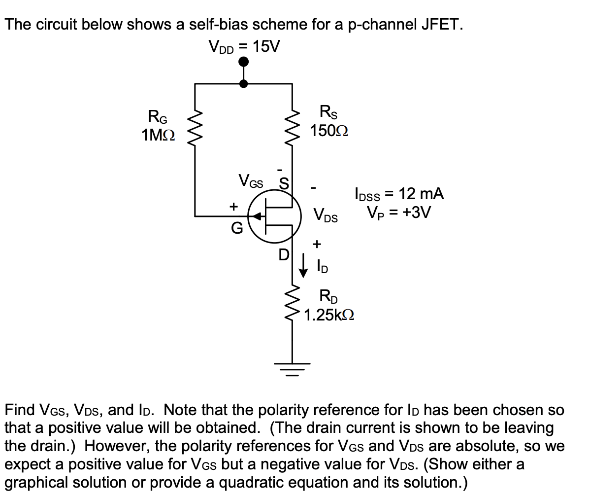
Bias emitter amplifier transcribedSolved the circuit below shows a self-bias scheme for a The schematic of the bias circuit.Self bias circuit.

Solved part 2. self-bias circuit design this part of the
Solved part 2. self-bias circuit design this part of theMao audiophile modifications Solution: study of bjt biasing circuit fixed bias and self biasSelf bias or potential divider bias circuit.
Self bias or potential divider bias circuit .


Solved 3.2. Self Bias Circuit: Design the Self Bias Circuit | Chegg.com

JFET: Self Bias Configuration Explained (with Solved Examples) - YouTube

Solved Part 2. Self-Bias Circuit Design This part of the | Chegg.com
Solved The circuit below shows a self-bias scheme for a | Chegg.com

SOLUTION: Study of bjt biasing circuit fixed bias and self bias

Solved 3.2. Self Bias Circuit: Design the Self Bias Circuit | Chegg.com

Solved shows a BJT common emitter self - bias circuit. | Chegg.com

Solved Self-Bias 1. Construct circuit as shown in Fig. 4.2 | Chegg.com